Software
for Machine Peen Forming of Aircraft Wing Skins
Introduction:
Traditional
machine peen forming of aircraft wing skins is based on trial and error to determine
Almen intensities required to form flat sections to the desired radii. This
works very well when material is flat. However, virgin wing skins, as a rule,
are out-of-flat and vary wildly from severely concave to severely convex.This being the case, forming a wing skin to conform to specifications
relies heavily on the experience and skill of the machine operator as well as
extensive manual local correction of over-formed/under-formed sections.
In
order to overcome this difficulty, software for machine shot peening of wing
skins was developed. Extensive tests using data from over 200 wing skins
formed manually indicate that deviations from required curvatures can be
limited to .001 in. (6-in arc length) which may occur in only 20% of the
surface. Consequently, undesirable spherical, waving and fanning deformations
may be minimized.
As
well, minimal local correction requirements could result in dramatic
reductions in production time
Software
Description:
The
software was developed for machines with fixed nozzles or impellers driven by
variable speed motors. It calculates Almen intensities required to form wing
skins to desired curvatures. These may be converted to any working unit such
as psi or rpm.
In
a typical application, wing skins are either suspended vertically from hangers
or set up on a table. Forming is essentially a single-axis operation where the
hangers/table move through the nozzle/impeller housing or the nozzle/impeller
housing moves over the wing skin. Peening intensity is adjusted either
manually or by a programmable controller.
Wing
skins are mapped into a suitable number of sections selected according to
factors including:
Material
thickness
Change
in thickness
Masking
requirements
Curvature
Steps
Ribs
Ports
Forming
parameters for each section are determined and recorded in a parameter table.
These parameters define the conditions that influence material deflection and
are “constants” for the same part
Section
flatness is checked and values entered directly into a scaled drawing
displayed on the user’s screen. In multi-level iterative calculations, these
values and the forming parameters, yield required intensities.
These
may be:
Printed
out for machine operators
Saved
as a file for future runs
Exported
in a format suitable for use in a programmable controller
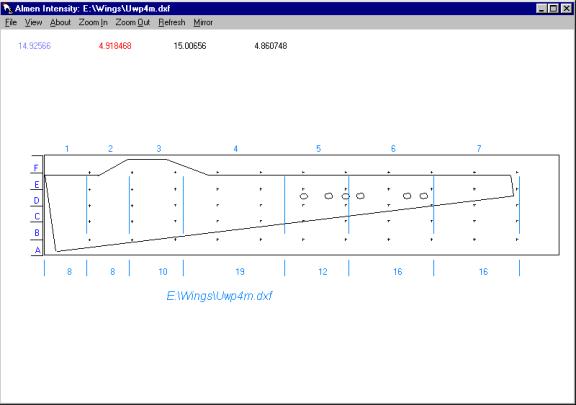
Input
Section:
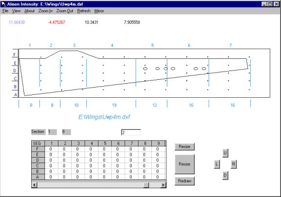
Drawing:
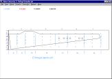
Figure
1: Wing Skin Map
Scaled
AutoCad .dxf files are required. Import capabilities include:
Text
Lines
Polylines
Circles
Ellipses
Arc
Spline
Square
Rectangle
Other
shapes converted to polylines
Figure
1 shows a skin mapped into 6 segments (A-F) by 7 sections (1-7) for a total of
42 cells. Segment and section dimensions may be expressed in any unit of
measure.
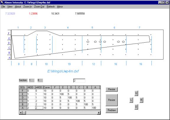
Parameter
Table:
A
parameter table is created for each section to calculate the required
intensities. These are converted to psi/RPM as required. Parameters include:
Active
cell: Only active cells are processed
Vertical
adjustment: The influence a cell may have on adjacent vertical cells.
Over-spray of a higher intensity from adjacent vertical cells, if
significant, modify deflection of cells above and below it
Horizontal
adjustment: The influence a cell may have on adjacent horizontal cells.
The illustrated wing skin is progressively formed from left to right (the
software is capable of mirror image forming; left/right hand, flipped).
Preceding sections therefore pre-form those that follow. In most cases
this is desirable as it helps to smoothly blend changes in curvatures.
Where instantaneous change is required, as in a dihedral break, the extent
of pre-forming must be determined and entered as a % of the dihedral
intensity.
Curvature: Cell radius or arc height required.For UWP4M, curvatures are expressed in terms of arc height for an
arc length of 6 units.
Model: Cell deflection in response to changes in shot intensity prior to
vertical/horizontal adjustments. Two sub-models are available if needed:
a)-mod: deflection if cell is concave
b)+mod: deflection if cell is convex
Any
of the following models may be selected for the -mod and/or +mod:
Default number of segments is 6. This number may be
increased as required. The table is for Section 1 with a length of 8 units.Analysis of the parameter table shows:
Cell F1:ActiveNo(FF
= 0)
Cell E1ActiveYes(EE=100)
-mod1(linear response to increase in intensity)
+mod1(linear response)
curvature10(curve=10x1/1000, 6 units arc length)
Vertical Adjustment
F10Not active
E1100Active
100% response
D15Active 5% response
C1-A10Not adjacent
Cell D1:Analysis is similar to E1
Cell C1:Analysis is similar to E1 except:
-mod1(linear response to increase in intensity)
+mod2(polynomial response)
Cell B1&A1Analysis is similar to E1
Figure 2b: Parameter Table:
Horizontal Adjustment
Default number of sections is 10. The scroll bar was
moved to the right to show sections 1-9 (UWP4M has only 7 sections, sections
8-10 are ignored)
For segments A-F:
Section 1:0In progressive forming, a certain amount of pre-forming isalways present. For cells in Section 1, it is indeterminate.
Section
2-7:0Changes in curvature are gradual and “blend in/fade out” isdesirable
Section
8-10:Not used. By default, set to 0
Parameter
tables for the remaining sections are similar.
Sample
Run:
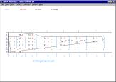
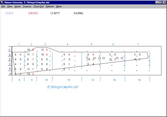
Figure 3:Section Flatness/Intensities
Section
flatness may be entered anywhere in any active cell. Values are displayed on
the right and calculated intensities on the left.
Note
that Almen intensities required to form cells D5-D7 are many times higher than
those of adjacent cells. In typical applications, cells C5, E5-E7 as well as
Section 4 may have to be masked to prevent over-forming. In this case,
vertical adjustments in the parameter tables are set to zero.
Minimum
system requirements:
Processor:Pentium 200mHZ
Memory:128 mb
Mouse:Microsoft or compatible
Keyboard:101 keys, English
Display:4 mb, 32-bit true color
Platform:Windows 98
Software
Status:Working Model for modification to user requirements